Marine ESS
A 10 kWh lithium-ion marine Energy Storage System (ESS)
Over the last decade, the large-distance sailing community has been noticing the performance advantages of lithium-ion batteries over lead-acid batteries and is steadily transitioning to this new technology. These marine energy storage systems (ESS) are unique as their requirements differ considerably from the more ubiquitous residential, automotive and recreational vehicle applications. Relevant requirements include fail-operate reliability, high bidirectional current capability and compatibility with a wide variety of legacy charger systems. Reliability is particularly important as the ESS powers everything from the refrigerator to navigational instruments and the bilge pumps.
For our sailing vessel, we desired to have such a system on board. While there are commercial players (Victron, Lithionics, Mastervolt) who cater to this niche, it was decided that our need provided an opportunity to sharpen my engineering skills. The following sections briefly discuss three parts of the ESS realized in this project. Parts not discussed here include building the photovoltaic charger setup, making a legacy lead-acid charger compatible with lithium-ion, the inverter setup, as well as most of the wiring and fusing.
This project was made possible by the outstanding documentation shared by Eric Bretscher of Nordkyndesign and by Rod Collins of MarineHowTo. Their research and, especially, their efforts to propagate their learnings are commendable.
Cell assemblies and fuse and relay board
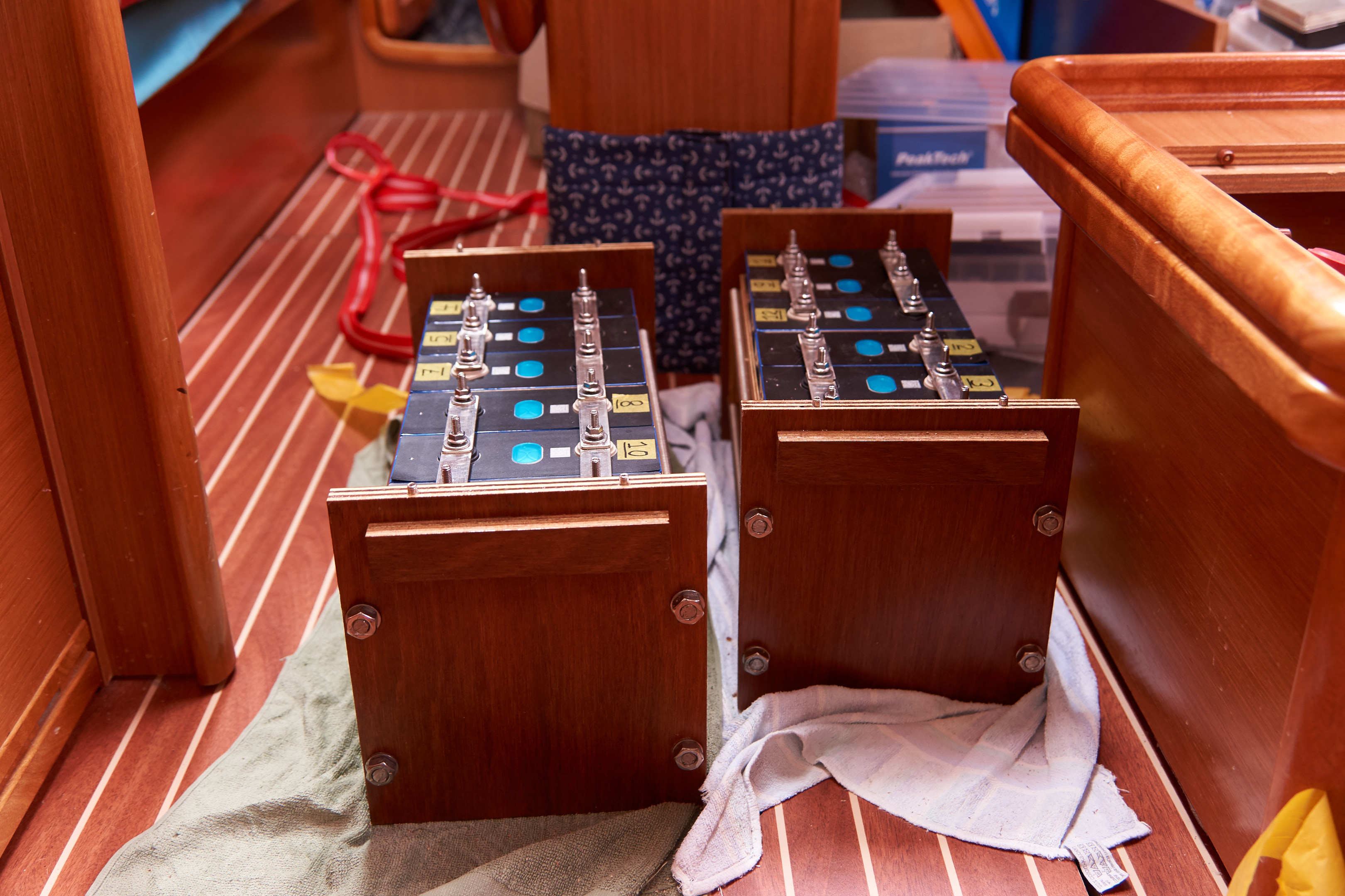
The battery bank consists of 12 LiFePO4 (LFP) cells 280 Ah each in a 3P4S configuration, yielding a total capacity of 840 Ah at 13.2 V, or about 10 kWh. Mass is 65 kg, less than the three 105 Ah lead-acid batteries it replaced. The cells were procured from China, while the pack casings were home-built from plywood and stainless threaded rods. Particular attention was paid to the protection of the cell’s electrical insulation. To ensure the pack would be manageable, it was split into the two 3P2S assemblies pictured below. These assemblies fit in the battery compartment with a twist-lock procedure, the play satisfying both ISO and ABYC standards.
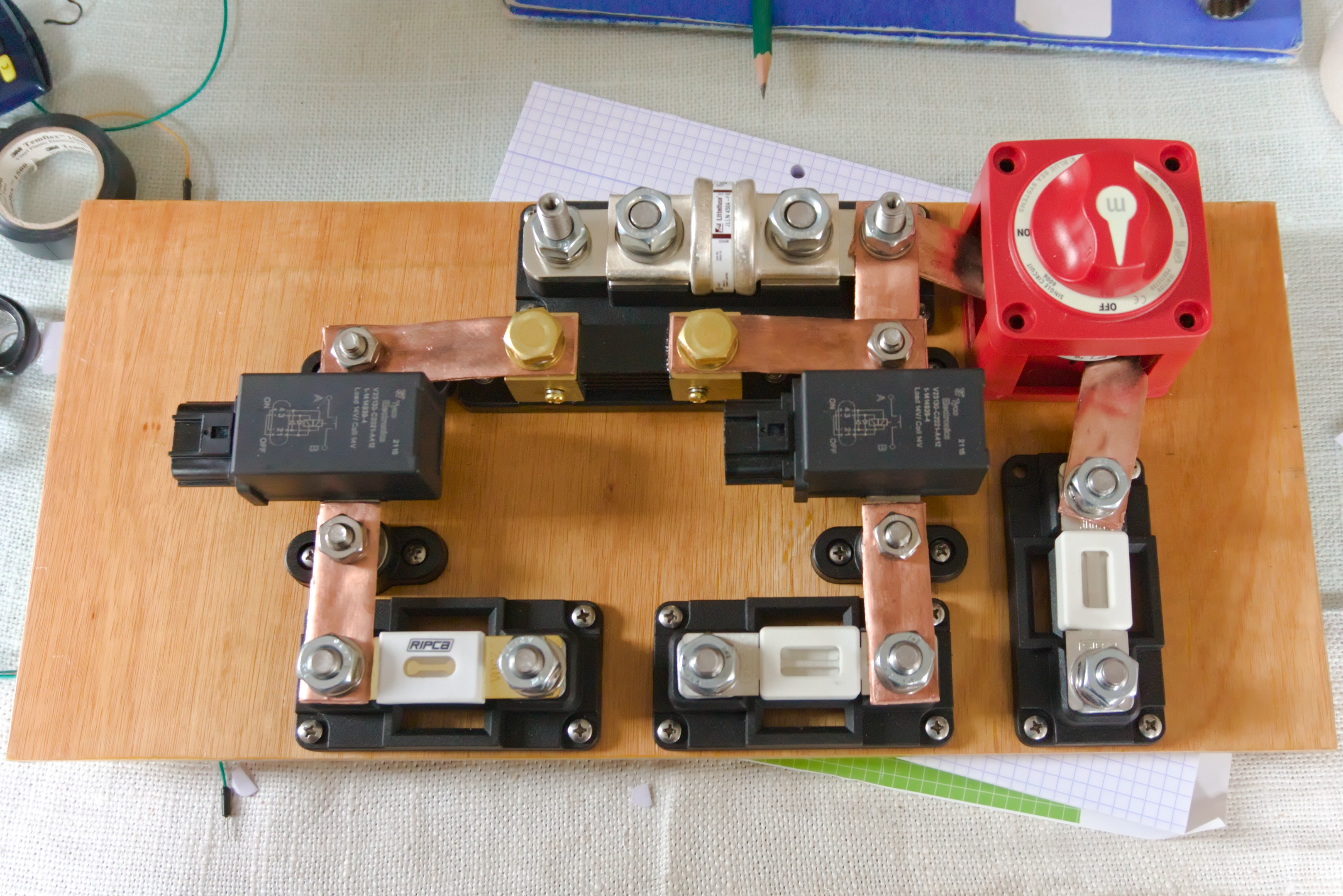
While LFP cells are intrinsically rather safe, in contrast to the popular NMC or LiPo cells, their combination of high capacity and low internal resistance does require appropriate attention on the fusing and insulation side. The fuse board, pictured below, sports a Class T main fuse with sufficient interrupting capacity. Adhering to best principles, the system has a dual-bus design with loads and chargers switched by respectively the load and charge bus relay. Both relays are latching to minimize quiescent current draw and are rated for 1500 A burst. Compared to a single-bus design, dual-bus allows for more granular fault mitigation.
BMS
In contrast to lead-acid batteries, lithium-ion batteries are almost always paired with a battery management system (BMS). The core purpose of the BMS is to ensure the system operates within safe limits, especially in case of partial system failure. The developed BMS control unit measures the current, cell voltages and temperatures and uses this information to drive the charge and load bus relays as appropriate.
As the BMS is the device that has all the necessary information available, it also centrally controls all chargers to ensure battery longevity. It also informs the crew with key metrics through the physical user interface.
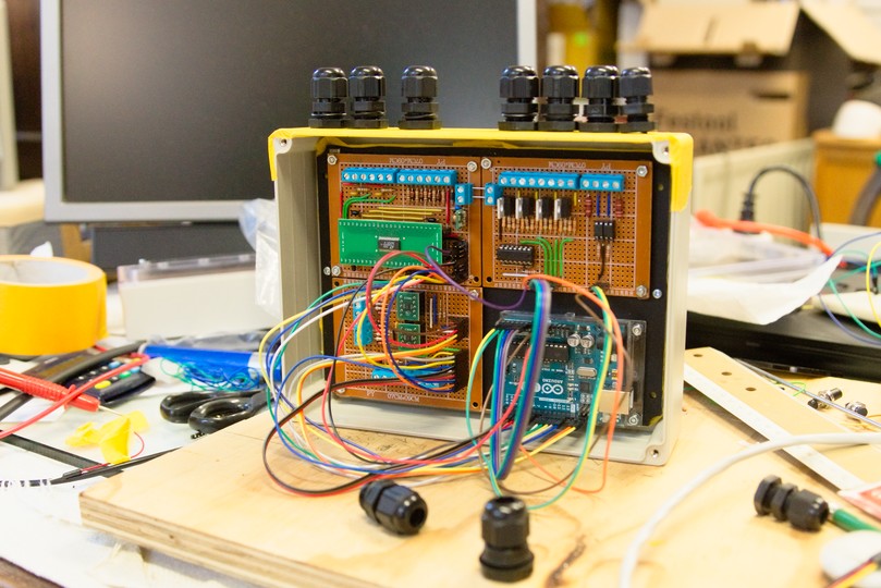
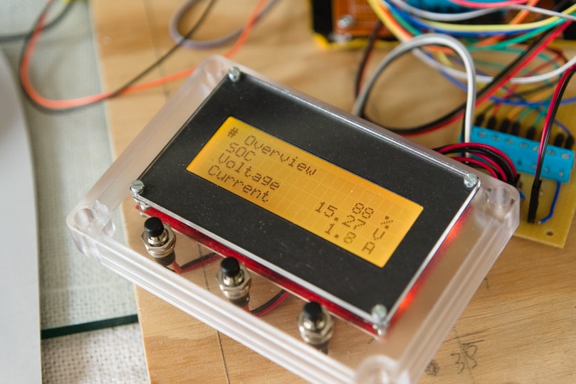
The two figures below show respectively the BMS control unit and the physical user interface. In the control unit, an Arduino Uno microcontroller board interfacing over SPI, I2C and UART runs the show. The physical user interface is equipped with a transflective LCD in combination with an orange backlight, ensuring excellent readability under conditions ranging from sunlit to nighttime watch all-lights-out. The State of Charge (SoC) is calculated as the numerical integral of current flowing in and out of the pack and is synchronized whenever a full charge is reached. Thanks to the high-accuracy measurement and estimation pipeline, the estimate drifts less than 1 % per month.
As the BMS was designed specifically for this niche use case, it possesses all the required features one would expect. For example, it tests for continuity through the latching relay coils every second to ensure the relays still are controllable (otherwise, relay wiring damage would cause the BMS actuators to fail silently). The SoC estimate is accompanied by an uncertainty estimate, allowing the former to be used in critical decision-making situations. Also, the BMS provides an auditive warning signal before cutting power, as demanded by ABYC E-13.
Alternator external field controller
A recurring theme in the changeover to lithium-ion is the engine alternator. While most of the energy is generated using photovoltaic panels, the engine alternator ensures electrical power is available at any desired time, for example, to power the bilge pumps for extended durations.
A first challenge is that, from the factory, these automotive alternators are equipped with a voltage regulator without current sensing. When combined with the low internal resistance of a lithium-ion bank, the built-in regulator pushes these machines into overcurrent territory, leading to overheating. The second challenge is that the alternator output is switched by the BMS using the charge bus relay, and is thus interrupted whenever the BMS decides (usually cell overvoltage). However, this current also goes through the alternator’s stator coil, which has a significant inductance, leading to a voltage spike when the relay opens the circuit while the alternator is generating current. This voltage spike of over 70 V tends to destroy most other electronics in parallel to the alternator.
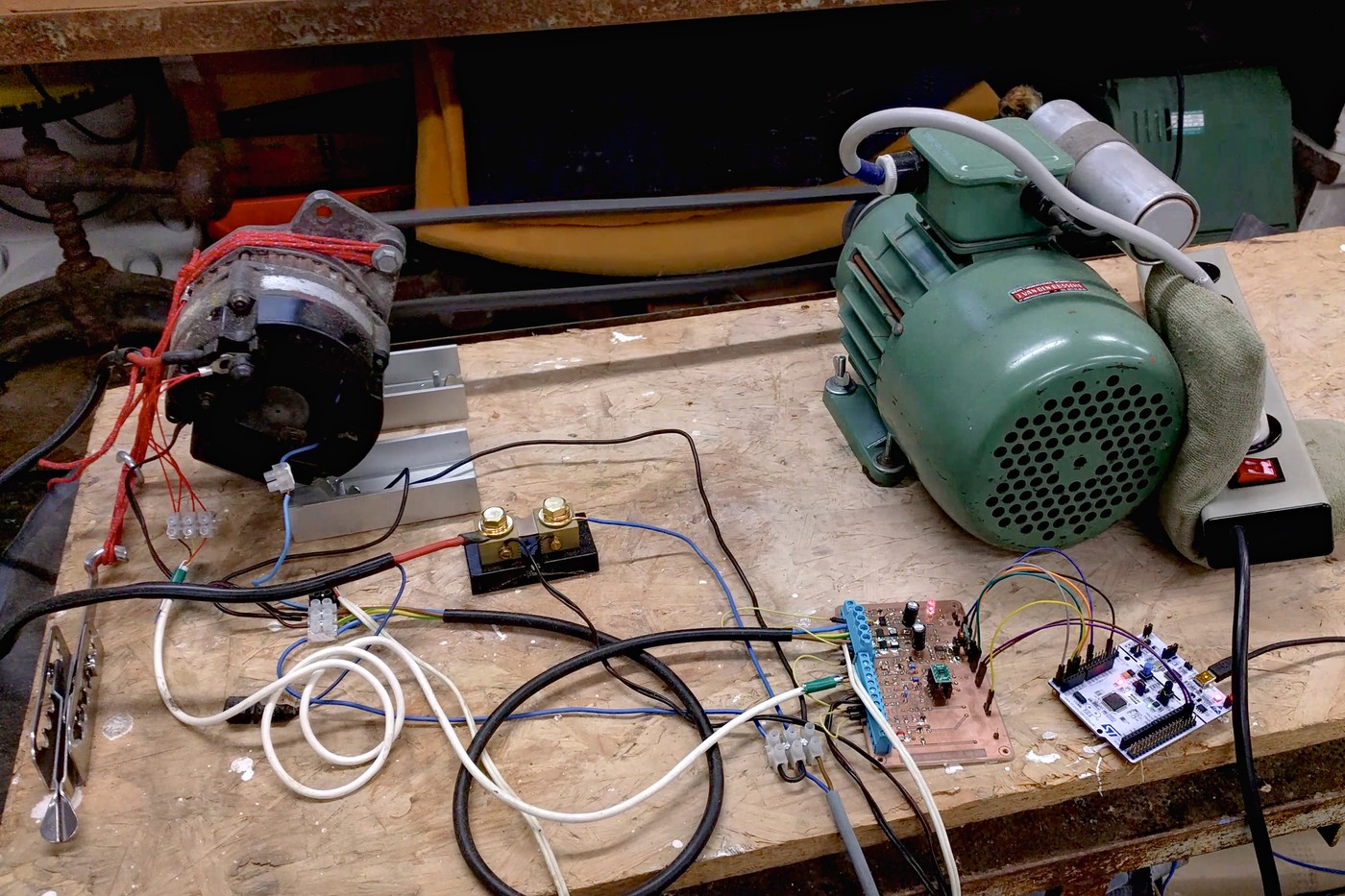
The first challenge was addressed with an external field controller that measures alternator current and temperatures in addition to voltage, to ensure the alternator operates within its nominal range. The two figures below illustrate the external field controller test setup. The first shows the automotive alternator on the left, connected by a belt to the induction machine on the right and lower right the microcontroller board and the developed PCB. The second figure shows the graphing display, plotting live metrics such as current and temperature. Tests included running the alternator in short circuit.
The second challenge was addressed through three design choices. The first choice was to go for a dual-bus setup with chargers and loads separated, putting the loads on a different circuit than the one where any alternator voltage spikes may occur. The second choice was to integrate the BMS and the field controller in the sense that the BMS stops asking the field controller to provide current a few seconds before opening the relay, allowing the alternator to shut down gracefully. The third choice was to ensure that the lead-acid starter battery remains always available as a current sink by preserving the split-charge diode. The starter battery is charged using a small DC-DC converter fed from the alternator output.
The alternator field regulator’s PCB, microcontroller and graphing software were developed from scratch, with the exception of some general purpose libraries. For the circuit inspiration was taken from the VSR Alternator Regulator project.

Evaluation
The system entered operation in September 2021 and has performed without any faults, including during a 23-day Atlantic crossing in February 2022. It fulfills our daily liveaboard energy needs, including refrigeration and electric cooking. Based on the limited available experiences of using LFP batteries properly in this niche application, the expected lifetime is over 15 years.
Aside of delivering a well-working system, this project taught me a lot. While I already had some experience with many of the concepts and skills (such a electronic circuit design), this project allowed me to level up and expand my toolbox, both technically and from a time management perspective, as this project ran alongside my master’s thesis.